I've always been interested in display technology, and this has driven my career into 3D graphics. But there's something to be said about the older, almost forgotten technologies. I have tinkered with Nixie tubes, of course, but wanted something new. Enter flip-disc displays.
Flip-disc displays work as you might suppose: a single pixel is a plastic disc mounted on an axis such that it can flip between two stable states; on or off. There are several ways of driving them but generally an electromagnet is involved. They are designed such that they require zero power once in a given state.
They're useful for any display that will primarily be seen in bright sunlight, where the low resolution is not a problem, and where low (or zero) standby power is important. They might remind you of old mechanical train station or airport displays and there are definite similaries in the technology.
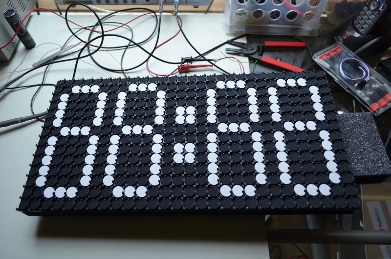
I purchased a 28x14 pixel display from Alpha-Zeta Ltd. in Poland. It's quite a nice looking unit:
I plan on getting it framed to that I can put it on a shelf, but in the meantime I have it bare.
This particular unit has an interesting mechanism. You can see it here in its off, in-between, and on states:
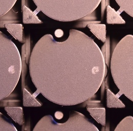
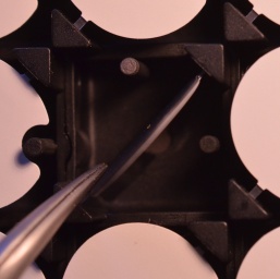
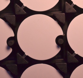
To understand how it works, first note the gray splotch on the right of the disc in the first image. This is an embedded permanent magnet. Second, note the two rods projecting toward the camera in the second image. These are the opposite poles of the electromagnet (which is embedded below the device), and is made from a material which retains its magnetization. The permanent magnet is only "happy" in one orientation or the other, depending on the direction of magnetization. So, if the disc is in one position, reversing the field will cause the disc to flip on its axis into its new stable orientation. Once in the new state, it will stay that way even once power is removed due to the remaining magnetization of the rods. I've found that the force is surprisingly strong and that it feels rather like there is a spring in there somewhere.
The discs themselves flip quite quickly. It appears almost instantaneous in this test:
You can see a lot more at high speed. This is 14x faster than real-time (sorry for the low res):
Fortunately, the unit came with all the necessary hardware to drive the electromagnets and interface with a microcontroller. The only issue is that it uses the RS-485 standard, which most microcontrollers do not support natively. I was using an Arduino, and while there are Arduino to RS-485 shields out there, I wanted to try driving it myself.
The RS-485 standard is very similar to the RS-232 that we all know and love, except that it uses a differential signal. Differential signals are more immune to noise because any voltages induced in one conductor tend to also be induced in the other conductor, and these voltages cancel out. As such, signals can travel for much longer distances compared to the non-differential alternative.
Wikipedia shows a nice diagram of the behavior of the signal:

As you can see, the U+ and U- signals are simple inversions of each other. There is the other characteristic that in the idle state, the voltages are close to each other (much closer than when sending bits). To achieve this, I first used the same resistor bias network shown on Wikipedia:
![]()
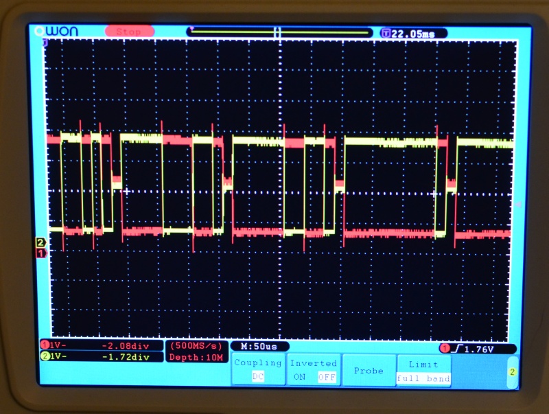
Second, I used the low-impedance state you get on GPIO pins that are set as inputs. When the pins are undriven, the bias network sets the output voltages to 2.3 V and 2.7 V (assuming a 5 V Vcc). When driven, the pins output the full 0 V to 5 V range. You can see the different levels on the oscilloscope:
Because the ATmega328 doesn't have a special serial mode for this, I used bit-banging to achieve the same effect. Actually, I was a tad bit more efficient--I used an interrupt that fired at 57,600 Hz. Using the TIMER1 unit on the ATMega, I can fire off an interrupt when the counter overflows. The counter is 16 bits, and so ordinarily would fire every 65536 clock cycles. However, the counter can be preloaded with any value, and so preloading with (65536 - desired_clocks) achieves the same effect. At 16 Mhz, I need to fire an interrupt every 278 clocks. This is a pretty straightforward bit of code:
The value "42" is empirically derived and basically a function of interrupt overhead (which is high on Arduino). I also disabled several other interrupts to lower overhead (by default, Arduinos have several interrupts going and this can cause random delays).
The interrupt handler itself is not much more complicated:
Every character sent requires 11 bit periods: a start bit, 8 data bits, a stop bit, and a low-impedance idle period. As you can see, I write to the ports directly instead of using digitalWrite and pinMode. These functions have extremely high overhead and even with back-to-back digitalWrite calls, there is a delay of something like 10 cycles. That's unacceptable for my purposes and so I just use the ports directly.
As you can see, I have to preload the timer counter upon each interrupt. Otherwise the ISR will only fire again after the full 65536 cycles.
So, you may ask, what do I do with such a display. Well, I have lots of plans, but the first thing I wanted to try is to make it remote controlled. I thought a touchscreen interface of some sort would be fun, so I decided to try to make it controllable from an Android app. Check it out!
It's pretty crude right now but you get the idea. The app translates touch points and button presses into a simple 2-byte protocol, which handles "disc on", "disc off", and a few "clear" commands. The bytes are sent over Bluetooth to a cheap receiver unit hooked up to the Arduino.
I have to say, although I find the Android programming environment pretty unpleasant, it was remarkably easy to get it running overall. To get a Bluetooth serial port up and running was not too many lines of Java:
"linvor" is the name of my device; if this were a real app I would add a selector. Note that funny "00001101-0000-1000-8000-00805F9B34FB" UUID! It happens that this is the magic UUID that you need to connect to a serial port device (this took rather too long to figure out...). After that, handling the touches is easy (sorry for the nasty hard-coded numbers; I plan on fixing this):
The Arduino side just does the reverse of this and sets a pixel at the specified address, as well as responding to full clear-to-black or clear-to-white commands.
So what's next? Ultimately I plan no having this in a nice display. It's currently off getting framed, and in the meantime I am adding various modes to the driving software: a clock, stock-ticker, various screensaver-type animations (Pong, say), and so on. Maybe even tweets from my cat's litterbox! Ultimately I hope to improve the app enough that I can make it public and visitors to my place can draw on the surface with their own phones or tablets. Perhaps even play a game (Pong, Snake, Tetris, etc.). So stay tuned for part 2... sometime. Shoot me a mail at scott at scottcutler dot net for questions.
Copyright 2014 Scott Cutler. All code may be used freely and is without warranty. Acknowledgement is preferred but not required.